
🤖 “I have detailed files” 🤖

Pre-tense
One of the biggest headaches an operator faces on a daily, even minute by minute basis is, ‘What happened in my network?’, ‘What was it like before?’, ‘What changed?”, “Who made a change?”, “When was the change made?” … etc.’.
And so leveraging a Data Mesh can support proactive analysis, as well as reactive alerts, alarms, whilst powering/ super charging automation … etc., for the likes of network monitoring, network management, event correlation and outcomes … etc.
This article wont get into ⛱ Datamesh or ❓What is a Data Mesh, however this blog will outline how the information coming from networking devices/ elements into a Data Mesh can be used and how disparate data can be used together in order to drive real outcomes.
It becomes self-aware at 2:14 a.m. Eastern time, August 29th
So where to start? On the basis that telemetry from the networking devices/ elements is already being captured in some form of collector and/ or data storage/ Data Mesh. Then if you’re sitting comfortably, then I will begin.

Terms of Reference
Before we dive too deep too quickly, here’s a quick recap of some terminology used regarding the hardware of a network device/ element.
So taking something like the ufiSpace S9510-28DC:
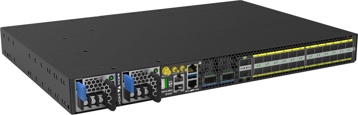
It it composed of the following elements:
Routing Engine - Intel Denverton-NS 4-Core @ 1.6GHz (Standard) or Intel Denverton-NS 8-Core @ 1.7GHz (Premium)
ASIC (Application-Specific Integrated Circuit) - Broadcom Qumran2a BCM88483
SerDes (serializer/deserializer) - 16 x 50G + 36 x 25G
Layout
What this will logically look like inside the ‘chassis’ (even if it is 1RU):
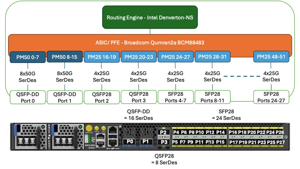
Routing Engine (RE) <> Packet Forward Engine (PFE) Relationship
The RE is the ‘brain’ of a networking element, it holds and processes all of the information that is given to the networking element, running configuration, firewall filters, QoS … etc., and the Routing Information Base (RIB).
The PFE is the ‘executer’ when it comes to decisions about where to route traffic/ packets. It is programmed by the RE, with the best available routes from the RIB to create the Forwarding Information Base (FIB).
Optical and SerDes
In order to support the port speeds, the SerDes bandwidth needs to equal or be higher than the optical interface, i.e.,
400GbE optical interface = 8x 50Gbps SerDes
100GbE optical interface = 4x 25Gbps SerDes
“Lasers”
So now it’s time to discuss light, wavelength (frequencies) and “lasers”.

All optical transceivers have a transmit (Tx) and receive (Rx), they usually use separate lasers and fibres to keep the optics separate, as the wavelength is the same for both the Tx and Rx:
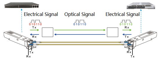
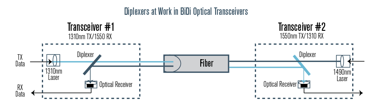
However in BiDirectional (BiDi) optics, there is only one laser, and therefore one fibre strand is needed, and so different wavelengths are used for the Tx and Rx.
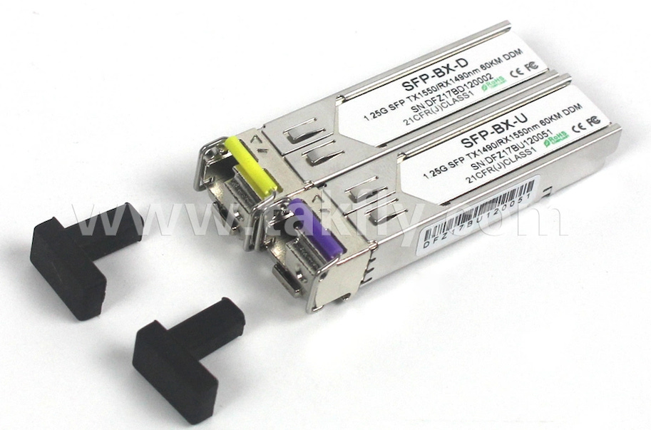
Note that the colours on the release handles of the transceivers delineate what the Tx wavelength is:
yellow = Tx 1550nm and Rx 1490nm
purple = Tx 1490nm and Rx 1550nm
Are You Sitting Comfortably? Then I’ll Begin
The importance of this morning and the relationship(s) between them is critical when operating modern networks.
The size and scale of modern infrastructure is now reaching the point that disaggregating to reduce the blast radius is becoming the norm, and so this increases the surface area that needs to be managed. Therefore, the number of network elements/ devices is always increasing.
So in order to trace a fault, or understand a change/ or impact … etc., understanding the relationship(s) between network elements/ devices and the effects they have on each other drives the operational excellence requirements of high quality monitoring and data collection. This is so any trend can be called out, any proactive intervention can be taken, any reactive troubleshooting can immediately identify the root cause and any investigation can have a play back history.
Here are some examples of how the data exhaust from these elements can be used.
CPU
PFE CPU is spiking and/ or is high and holding constant, however the RE CPU is low
This can mean that there is some large routing updates being programmed and or large amounts of traffic are being sent through this PFE. If this scenario continues to any period of time then the PFE might become overwhelmed and start dropping packets.
The RE is spiking and/ or is high and holding constant, however the RE CPU is low
This could be due to a large amount of routing updates occurring in the network, and as such this behaviour will be seen on many devices or there could be something local to the device and causing a large amount of logs to be generated. The slower the CPU the longer the updates will take, and if the updates continue to flood (i.e., a link(s) flapping), then smaller devices can get overwhelmed.
Memory
Interfaces
Examples
The following are examples where the light levels were previously fine and had a ‘lit’ and working service(s) over the interface(s).
Rx Light Dropping
This can be caused by problems on the fibre(s) between the devices, to the Tx laser on the adjoining device (whether that is an optical shelf or a network router … etc.).
Trend data is very important here as well as the light levels of the device physically attached to it, i.e., if there is an optical chassis for long distance networks (LDN), i.e., are the levels trending down over time, or just fluctuating?
If a downward trend, have move services been added to the fibre path?
If fluctuating, are there any ground works in the area? i.e, giant yellow fibre finders.
Tx and Rx Light is Dropping
This can be quickly narrowed down to, is it just one port, or are others affected (see and how some ports share PHY on the ASIC).
If it is a single port, then what is the age of the optical transceiver?
If it’s the adjacent ports sharing the PHY , are they all affected to the same magnitude and at the same time? i.e., lack of power, and or increasing temperature; as the higher the bandwidth and the further the distance a transceiver can operator over, the more heat and power it creates and needs.
Temperature
The Inlet Temperature is Rising, However the Environmental Temperature Isn’t
This could be a symptom of the environment not managing to clear away the hot/ warm air produced by the network element/ device.
The Fan Speed is Increasing/ Fluctuating, However the Environmental Temperature Isn’t
This can be caused by a few factors:
The network element/ device is under load, and the CPUs are running hot, so the system increases the fan speeds to clear the air off the CPU heatsink(s).
The bearings in the fan could be failing, causing the fan to spin more freely/ faster.
The solenoid/ sensor could be failing, causing the fans to spin erratically.
Power
Additional References
Inlet Temperature Ratings
Telco Vendors
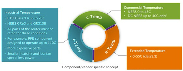
c-Temp
Commercial Temperature
NEBS 0 to 45*C
DC NEBS up to 40*C only
e-Temp
Extended Temperature
0-55C (class3.3)
i-Temp
Industrial Temperature
ETSI Class 3.4 up to 70C
NEBS GR63 and GR3108
All parts of the router must be rated for these conditions
For example: PFE component designed to operate up to 110*C
More expensive parts
Smaller heatsink and less fan speed: less power
Industry (including Optics) broader standards
Commercial: 0 °C to 70 °C (32 to 158 °F)
Industrial: −40 °C to 85 °C (−40 to 185 °F)
Military: −55 °C to 125 °C (−67 to 257 °F)
So Where Do We Go From Here?
Well if you’ve made it this far, well done. The answer you’re looking for is … Data Mesh.
Now as per the pre-tence, whilst I won’t get into the details of Data Mesh, the principal is; gather data in the most efficient way for it, and for your organisation, then build the relationships between the data/ nodes that are right for your organisation. Graph Databases/ GraphQL are great for this, however scaling and experience of Graph will play a big role in how you deploy this.
Granted the more network elements/ devices you have, and the more data points you collect the larger the data storage you’ll need and the better data retention policy you’ll need for ‘hot data’ (instant), ‘warm data’ (the recent period) and ‘cold data’ (long term).