
🎶 Do you want to find a Network? 🎶

Pre-tence
In any network engineers career comes the time you need to adopt and/ or operate a network which has already been created. And before you can work on capacity vs. utilisation, you must first achieve enlightenment around what devices are in the network, and what relationship do they have to the other devices and elements in the network.

So putting my best singing voice on and in the tune of Yentl/ Frozen I respond 🎶 Yes, I want to find a Network? 🎶

What Are the Main Problems/ Pain Points?
The detail of the information at the right level of the documentation.
The ease of interrogating said data.
And the validity of the data stored in the various repositories.
Examples
Device Upgrades
A device at the edge of the network gets upgraded either to a new model or a whole new vendor, if the documentation isn’t updated then:
engineers will be confused either when the attend site and can’t easily find the device (assuming device labels are still in size 8 font due to lack of facia space).
when the log on to it remotely to troubleshoot or configure a new service.
the automation breaks causing services not to be provisioned and if there’s no monitoring this could be broken for a while.
Maintenances and Change Control
Without device to device relationship knowledge and/ or provisioned service, working out which services could be impacted by a maintenance under change control get’s real difficult real fast.
And in a post incident review, it can get very messy working this out.

Where to Start?
Most organisations will have a network diagram, which will at least cover the PoP to PoP connectivity or relationships, however these will predominately be commercial or marketing focused (or curated), so for a network engineer, this has limited value and to a network operator, if fairly useless, other than knowing which facilities to go a inspect (or look for the bill from).
Example: PCCW/Console Connect
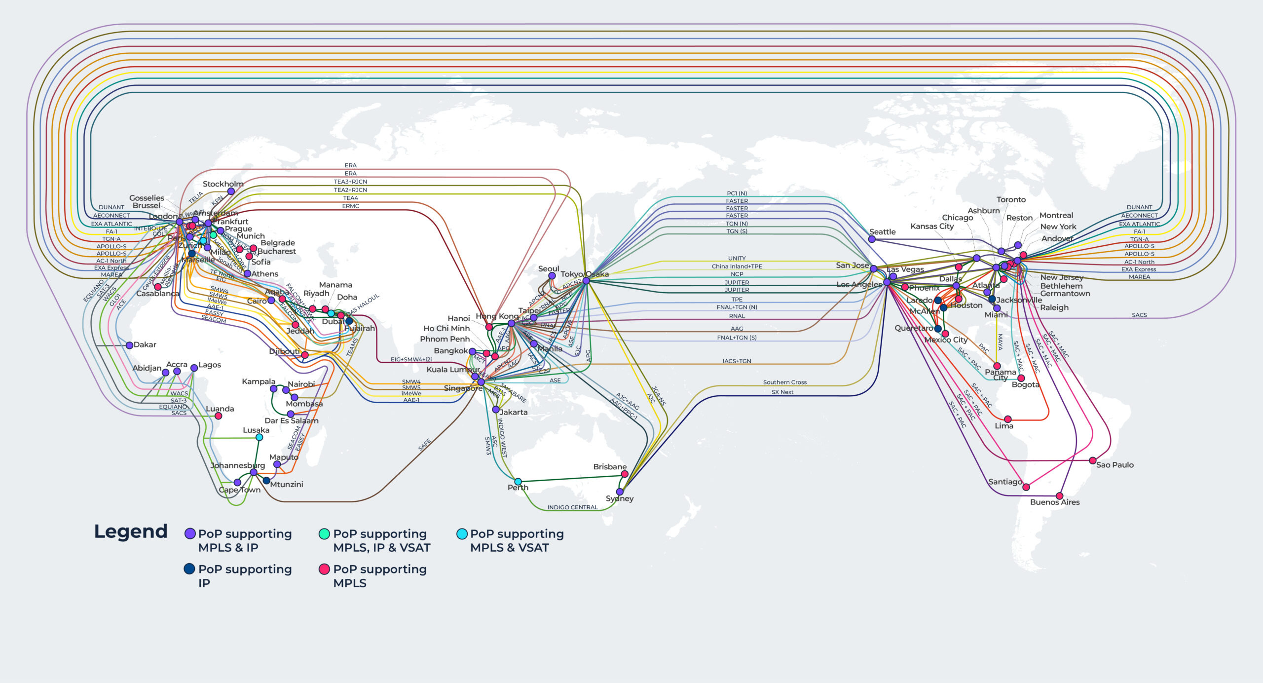
Looks pretty, however it only offers up information regarding city to city connectivity, not which PoPs within said city connect to each other … etc.
The Devil is in the Detail(s)
Depending on the size of a network, there will usually be diagrams showing the following layers:
World
Continent (if required)
Region, Theatre and/ or Territory
PoP
Rack
Cabinet (say in the street)
Duct
However keeping the detail(s) of this information up-to-date is tricky, so the diagrams will hopefully show:
PoP/ Device hostname (maybe a vendor logo).
Link speeds (usually by using colours and ownership).
PoP/ Device to Device relationships/ links.
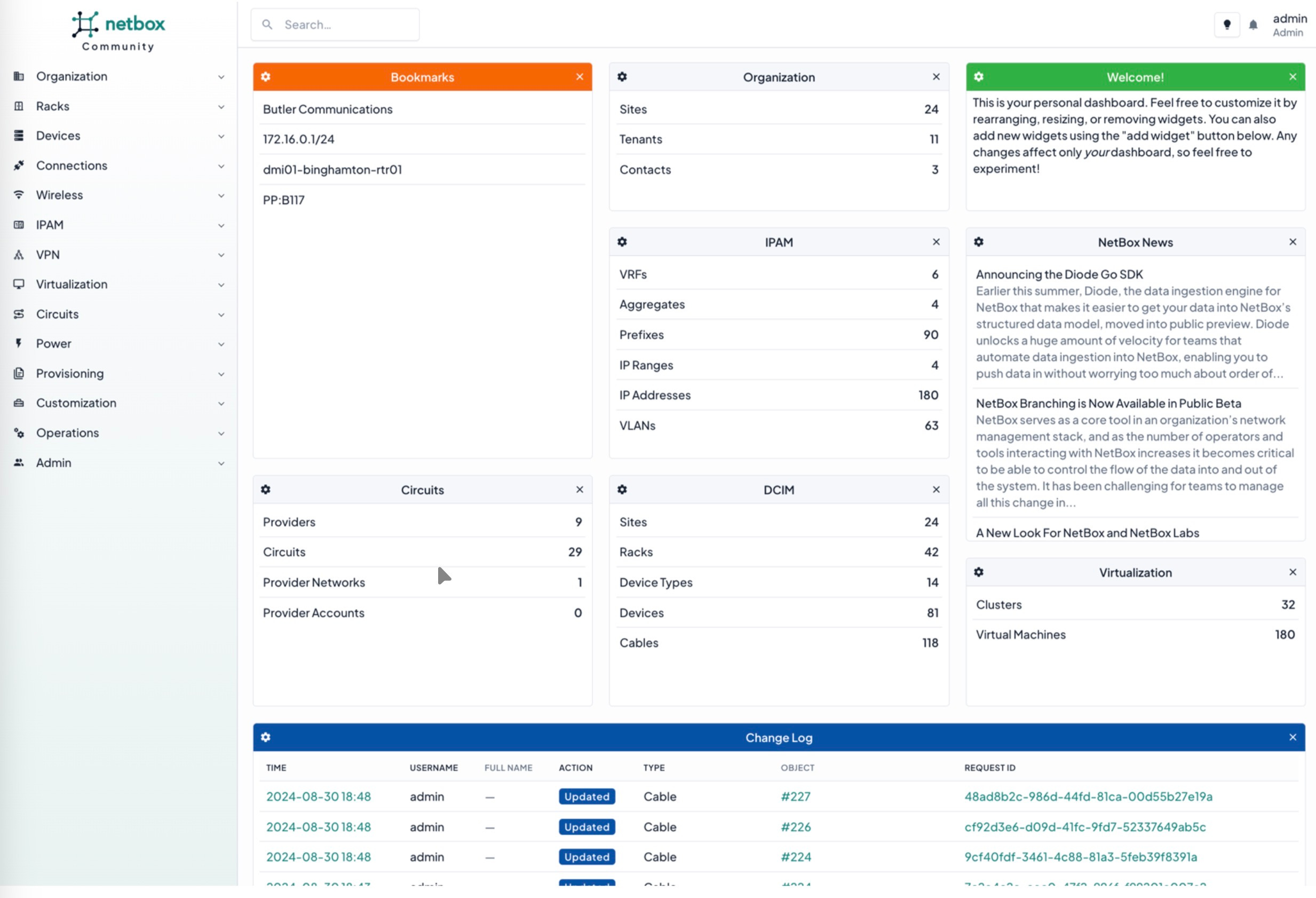
Another repository is the CMBD/ inventory management system, as at a minimum IP addresses, cross connects, circuits and device locations should be recorded here for basic NOC operations.
However without automation and audits, this repository of information can quickly fall out of sync with what is deployed in a network.
Example: Netbox
So How Do We Find the Detail?
The only ‘source of truth’ is the network itself, so the network needs to be interrogated and using the following guidance.


Guidance
Find out the following for a single device that you have access to:
What is the device?
Vendor
Model
NOS
hostname (the one actually configured on the device)
What is its role? Provider Edge (PE), Broadband Network Gateway (BNG), P-Node (Core), Aggregation … etc.
What IP addresses does it have?
Loopbacks
Physical Interface Address(es) (IFD)
Logical Interface Address(es) (ILF)
What routing protocols is it running?
What are it’s neighbours? (yes the routing protocols want to be good friends).
How many Address Resolution Protocol (ARP) entries are there on the interface?
What is the description on the interface?
If an IFL what is the relationship of the description to the description on the IFD?
Parameters and Relationships
So lets say, you’ve logged into a device and you have most of the information above, what do the values of those outputs give you and what parameters can be applied to start working out the next move to discover the network?

What is the Device <> What is it’s role
So you’ve found out that the device is say a Juniper ACX or a Nokia 7200 series and its hostname is pe01.locationX and by applying some logic we can start to ascertain that specific vendors models abilities and draw out first conclusion based on the following::
Storage
Create an Interface record to the Network Knowledge Graph against the device entry.
Additional Data Required?
Vendor Knowledge Graph, i.e., key scaling information, and supported features on a per vendor/ model basis.
Current business architecture rules, i.e., an ACX =/= a P-Node.
Parameters
hostname seems to indicate a PE role.
the vendor model capabilities mean that it is NOT capable of being a BNG.
the scale of the network and/ or the business logic means that is NOT capable of being and/ or will never be used for a P-Node.
Conclusion
High probability of being a PE.
IP Addresses <> Device Neighbourship
Whilst in networking, when devices form neighbourships, they’re not always “good friends” (see EANTC interoperability test reports), the data point and the values are key to understanding is the link point-to-point or a wider layer 2 network (LAN/ WAN … etc.).

So you’ve found that one of the interfaces IFD or IFL is a IPv4 /31 and IPv6 /127, and the interface is UP. Next you find that there is only 1x ARP entry and/ or 2x IPv6 neighbours on the IFD or IFL, we can now draw a second conclusion based on:
Storage
Create an IP record to the Network Knowledge Graph against the Interface entry.
Additional Data Required?
CMBD IPAM.
Parameters
IPv4 /31 and IPv6 /127 indicate a point-to-point link.
1x ARP and 2x IPv6 neighbours entries (1x entry for the configured /127 and 1x entry for the automatically generated private address) indicate a point-to-point link.
Conclusion
There are no other devices on this interface.
Description <> Device Neighbourship (with an IP address(es))
So you’ve found that one of the interfaces IFD or IFL has a unique description, there’s an IP address and the interface is UP. The description might be something like ‘P2P CR01 <> CR02’ or ‘LINX LAN’ … etc., so with the IP Address the usage for the interface can be drawn and/ or cross checked.
Storage
Create an Description record to the Network Knowledge Graph against the Interface entry.
Additional Data Required?
CMBD IPAM.
CRM/ CMDB circuit list.
Parameters
Apply the necessary business logic and correspond that with the IP address stored for that interface in the Network Knowledge Graph to determine the interfaces usage.
CR indicates the interface could be a core link.
LINX indicates indicates the interfaces could be a public peering LAN.
POxx or AExx usually indicates a port-group or aggregated ethernet interface.
Conclusion
Subject to business logic, however it should not be used as a deciding factor for the interfaces usage, i.e., the interface might say ‘Office LAN’, however the IP address is a public one assigned to a public peering LAN.
Description <> Device Neighbourship (without an IP address(es))
So you’ve found that one of the interfaces IFD or IFL has a unique description, however whilst there is no IP Address assigned, the interface is UP.
The next thing to look for is whether there is any layer 2 configuration on the port, i.e., is it part of a port group/ Link Aggregation Control Protocol (LACP) group or does it just have a VLAN assigned?
Finally are there any Media Access Control (MAC) address entries on the port?
Storage
Create an Description record to the Network Knowledge Graph against the Interface entry.
Additional Data Required?
CRM/ CMDB circuit list.
Parameters
Apply the necessary business logic and correspond that with the description in the Network Knowledge Graph to determine the interfaces usage.
APxx usually means access-point (wireless) and only needs a layer 2 interface back to the default gateway.
CUSTxx usually a end-user/ subscriber facing port.
Conclusion
It is a layer 2 interface, and therefore most likely not a P2P. It will be part of a wider switching domain and as such needs to have all interfaces associated with the switching domain correctly identified, recorded and associated with a switching domain record.
Protocols
So, you want to to use protocols to discover a network, then choose wisely:

Link Level Discovery Protocol (LLDP)
One of the most useful protocols, however it is a security vulnerability vector, so a lot of operators turn it off completely.
If switched on for internal links (i.e., links within an operators Autonomous System (AS)), it can help you establish so very useful information about the devices directly connected to the element being investigated.
Example: Juniper
cr01.lab> show lldp neighbors
Local Interface	Parent Interface	Chassis Id		Port
fxp0 		- 			64:9d:99:aa:aa:aa 	Gig0/1
xe-0/1/7 	- 			64:9d:99:bb:bb:bb 	TGi0/1
et-0/0/1 - 64:9d:99:cc:cc:cc HundredGigabitEth0/1Example: FS Switch
cs01.lab#show lldp neighbors
Capability codes:
(R) Router, (B) Bridge, (T) Telephone, (C) DOCSIS Cable Device
(W) WLAN Access Point, (P) Repeater, (S) Station, (O) Other
System Name	Local Intf 	Port ID
vmh01.lab	Te0/5 		vmnic5
Unknown 	Te0/6 		b47a.f1aa.aaaa
Unknown 	Te0/8 		ecb1.d7bb.bbbb
Unknown 	Te0/9 		ecb1.d7cc.cccc
Unknown		Te0/10 		ecb1.d7dd.dddd
Unknown 	Te0/45 		d067.26ee.eeee
Unknown 	Te0/46 		PCI-E Slot 2, Port1
Unknown 	Te0/47 		PCI-E Slot 2, Port2
cs02.lab 	Hu0/49 		HundredGigabitEth0/1
cs02.lab 	Hu0/50 		HundredGigabitEth0/2
cs03.lab 	Hu0/51 		HundredGigabitEth0/3
cs04.lab 	Hu0/52 		HundredGigabitEth0/4
cr01.lab 	Hu0/53 		et-0/0/1
br01.lab 	Hu0/54 		1/1/c2/1
os01.lab 	Mg0 		Gig0/2
ISIS
Without getting deep into the ISIS vs. OSPF debate, ISIS is a powerful Interior Gateway Protocol (IGP) and has many fields associated with it to aid in understanding what devices are connected to the element being investigated.
Example: Juniper
cr01.lab> show isis adjacency
Interface 	System		L State 	Hold (secs)
et-0/0/0.0 	cr02.lab 	2 Up 		19
et-0/0/1.89 	br01.lab 	2 Up 		24
et-0/0/1.94 	vr20.lab 	2 Up 		26
Summary
Follow the link state and ARP and you’ll discover some weird and wonderful things in your network.